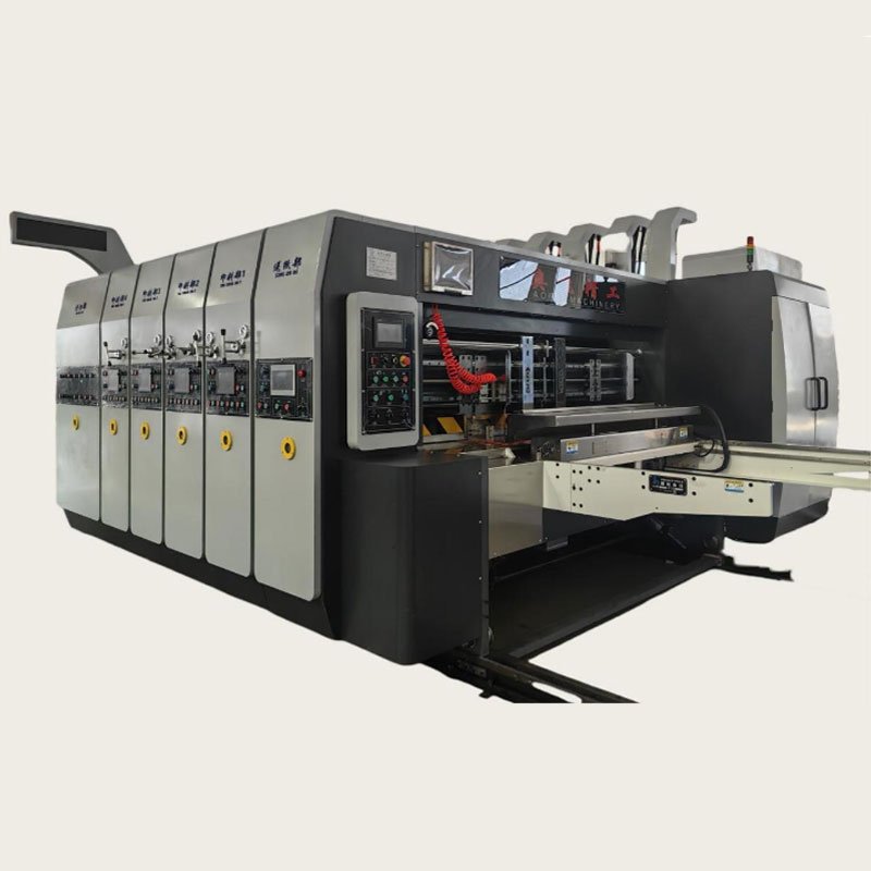
Functional Configuration and Technical Parameters
1. Paper Feeding Section
1.1 Machine Platform Combination
The extended pressure-free paper feeding system adopts a guide roller-free vacuum absorption feeding design, eliminating the need for rubber press rollers. The cardboard is directly conveyed to the printing unit through a suction belt system.
The feeding section is driven by a power input shaft synchronized with the front feed wheel and vacuum cylinder, ensuring smooth operation without deformation of the cardboard. The vacuum system shortens operation time while maintaining simple and convenient fine-tuning.
The separation between paper feeding and leading edge ensures accurate paper positioning and smooth board transport. The lifting platform significantly reduces frictional resistance and cardboard damage.
This machine is highly efficient for different cardboard thicknesses, enabling stable feeding even for warped boards. The fan-type vacuum and high-pressure suction box ensure high-speed operation without slippage.
The suction and transmission rollers are coated with anti-slip rubber for lasting durability. The system solves the problem of excessive wear caused by rubber rollers, ensuring that the board runs smoothly with high feeding accuracy and stability—perfectly meeting the production requirements of carton plants.
1.2 Machine Combination Features
- The automatic control console includes an alarm safety system (plug-in connection; allows disconnection and continuous warning signal), ensuring operator safety.
- Equipped with pneumatic locking device for secure connection between sections.
- The main motor and fan adopt frequency conversion control, ensuring energy saving (up to 30%), stable startup, and built-in overload protection.
1.3 Front Edge Feeding System
- Vacuum-assisted feeding with 7.5kW blower. Air volume is adjustable according to the curvature of the cardboard, ensuring smooth paper delivery.
- Paper pickup mechanism adopts pneumatic push rod for fast, smooth action.
- Side guide plates: Electrically adjustable; front and rear guides are manually/automatically adjusted.
- Taiwan-imported feeding belts—durable and wear resistant.
- Isolation feeding switch—optional based on production needs.
- 7-inch touchscreen display showing production quantity, counting, and feeding time adjustment.
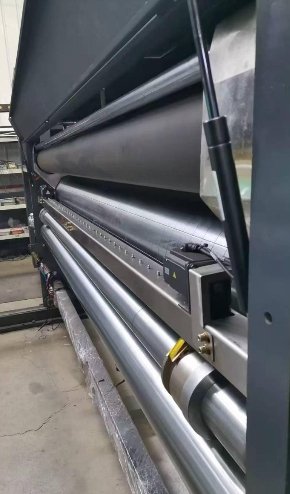
1.4 Dust Removal System
Equipped with a brush dust removal unit to clean dust and fiber particles from the cardboard surface before printing, improving print clarity and overall print quality.
2. Printing Section (Optional 1–4 colors)

2.1 Printing Rollers
- Outer diameter: 468 mm (with plate: 480 mm)
- Steel roller surface ground and chrome plated.
- Dynamic balance adjustment ensures smooth rotation.
- Fixed plate cylinder guarantees stable printing accuracy.
- Universal hanging rod with 9 mm notched brackets.
- Foot pedal control for automatic reverse rotation when cleaning plates.
- Plate gap adjustment is electrical for precise control.
2.2 Impression Rollers
- Outer diameter: 156 mm
- Steel roller surface ground and hardened with chrome coating.
- Dynamic balancing ensures smooth rotation.
- Roller gap electronically adjustable from 0–12 mm.
2.3 Upper and Lower Paper Conveying Rollers

- Upper roller diameter: 99 mm, thick-walled precision tube, two electrical pressure adjustment rollers.
- Lower roller diameter: 156 mm, thick-walled precision tube, surface ground and chromed.
- Conveying roller gap adjustable by dial, with a range of 0–12 mm.
2.4 Anilox Roller

- Outer diameter: 213 mm (optional sizes: 180, 200, 220, 240, 260 mm)
- Steel roller surface is ground, engraved, and chrome plated.
- Balanced rotation ensures even ink transfer.
- Equipped with automatic cleaning device for anilox roller.
- Ink amount can be manually adjusted via dial.
2.5 Rubber Roller
- Outer diameter: 200 mm
- Rubber surface coated with wear-resistant layer; dynamic balance calibration.
- High-precision ink distribution ensures uniform color consistency.
- Hardness: 60–65 Shore for enhanced durability.
2.6 Register Adjusting System
- Planetary gear mechanism provides 360° electric phase adjustment, operational during run or stop.
- Longitudinal register manually adjustable: ±10 mm.
2.7 Ink Circulation System
- Equipped with pneumatic diaphragm pump, providing consistent ink supply for better printing stability.
- Includes ink filtration to prevent dust or impurities entering ink system.
2.8 Lubrication System & Oil Supply
- Pneumatic type doctor-blade cleaning system to maintain clean rollers.
- Mechanical lubrication with circulating oil for all gears and bearings, ensuring even oil distribution and prolonged life.
3. Slotting Section

3.1 Lower Knife Shaft
- Outer diameter: Φ437 mm (excluding knives)
- Material: High-quality steel, ground and chrome plated.
- Dynamic balance correction for smooth running.
- Fixed base hole distance: 100 mm × 100 mm.
- Standard knife groove depth: 25.4 mm
- Slotting thickness: 16 mm (three-layer) or 13–15 mm (five-layer).
3.2 Upper Creasing Shaft
- Outer diameter: Φ434.2 mm
- Steel roller surface ground and chrome plated.
- Dynamic balancing for high precision rotation.
- Electrically controlled knife positioning synchronized with knife gap.
- Rubber pad thickness: 10 mm (outer diameter Φ454.2 mm, width 250 mm)
3.3 Creasing and Die Cutting Section
- Mechanical lateral movement ±40 mm for even pressure and longer rubber pad life.
- Reversible pad system improves usage lifetime (replace every 3–4 times only).
- Automatic electric control adjustment for efficient changeover.
- Die-cutting alignment precision within ±0.5 mm, ensuring accuracy.
3.4 Slotting Knife Device
- Segmented adjustment system; slotting and die cutting can be performed simultaneously, eliminating need for frequent plate changes.
- Quick-adjust pressure line and knife depth by electric memory system—one-touch setup, energy-saving and efficient.
4. Transmission Gear Section
- All gears made from 40Cr high-quality steel, heat-treated, ground, and oxidized.
- Using helical gears (HRC55–60 hardness) for smooth, quiet, and long-life operation.
- All moving shafts adopt keyless locking coupling, eliminating backlash for stable torque transmission.
5. Lubrication System
- Mechanical gear pump with circular oil supply system.
- Even oil distribution across gears for enhanced precision.
- Optional oil mist or spray lubrication to extend component life.
6. Technical Specifications
| Model | 480×3000 Front Edge Feeding 3-Color Printing Slotting Die Cutter |
|---|---|
| Feeding Width | 3000 mm |
| Design Speed | 260 pcs/min |
| Working Speed | 180–200 pcs/min |
| Max Sheet Size | 2700 × 1400 mm |
| Min Sheet Size | 450 × 600 mm |
| Max Printing Size | 2600 × 1400 mm |
| Max Slotting Size | 2700 × 1600 mm |
| Slot Depth (Adjustable) | 7 × 300 mm (customizable) |
| Plate Thickness | 7.2 mm |
| Main Motor Power | 11 kW |
| Fan Motor Power | 7.5 kW |
| Production Power Consumption | 45 kW |
| Overall Accuracy | ±1 mm |
| Slotting Accuracy | ±1 mm |